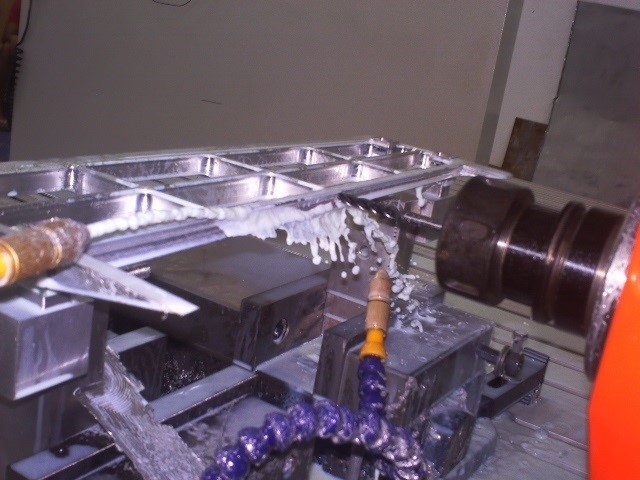
CAM SIMULATION PERSONAL CONCEPT COPYRIGHT
CAM SIMULATION PERSONAL CONCEPT COPYRIGHT
Video
—
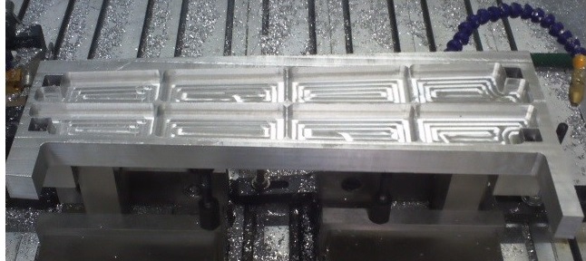
Posted: November 26, 2013 in CNC MANUFACTURING CAM SIMULATIONS, PNEUMATIC DISTRIBUTOR TMHK PROJECT
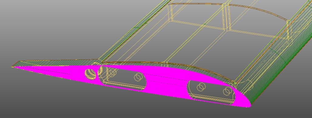
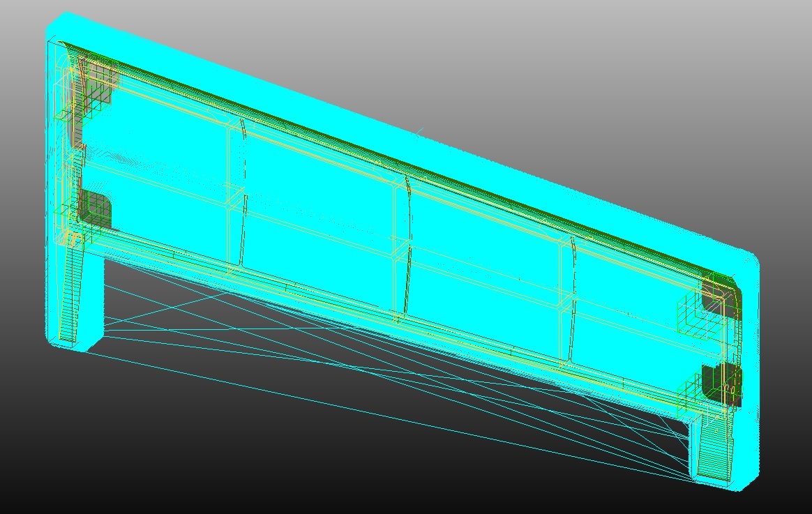
3D DESIGN PERSONAL CONCEPT COPYRIGHT
Video
—
Posted: November 26, 2013 in 3D CAD DESIGNS
The platform have 6 points of freedom. The design combines multiple designs found on internet. The kinematics have been tested in SolidWorks and can be adapted.
Video
—
Posted: November 26, 2013 in 3D CAD DESIGNS


The design with the 5 scoops burried into the fuselage increases the flow into the engines intake. The NACA profiles are carefully determined for the intake to keep the lowest possible drag force.
Image
—
Posted: November 26, 2013 in FLOW SIMULATIONS WATER AND AIR, TOMAHAWK Personal Concept
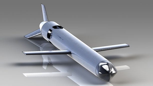
The nose shape will improve stability to compensate the centrifugal force caused by the engine.
Image
—
Posted: November 26, 2013 in TOMAHAWK Personal Concept

I added 5 scoop intakes for a better flow. The intake profiles are NACA.
Image
—
Posted: November 26, 2013 in TOMAHAWK Personal Concept
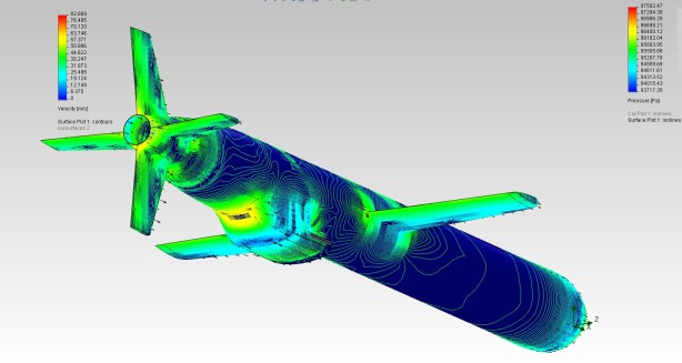
This is a simulation of pressure points according to different speeds.
Image
—
Posted: November 26, 2013 in FLOW SIMULATIONS WATER AND AIR, TOMAHAWK Personal Concept

This is a simulation of pressure points according to different speeds
Image
—
Posted: November 26, 2013 in FLOW SIMULATIONS WATER AND AIR, TOMAHAWK Personal Concept

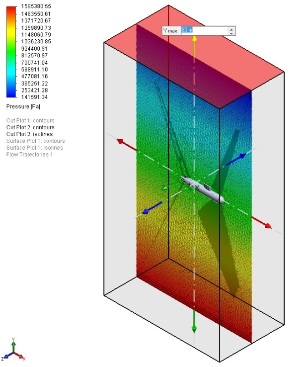
This simulation have been created to ensure that the structure will hold at different depths. The maximum depth was simulated to 80 meters.
Image
—
Posted: November 26, 2013 in FLOW SIMULATIONS WATER AND AIR
